Supplying alternating current to a coil
Supplying alternating current to a coil which is free to rotate in a magnetic field will not produce a motor effect since the current is constantly changing direction. Use is therefore made in an induction or squirrel cage motor of a rotating magnetic field produced by three separately phased windings in the stator.
The rotor has a series of copper conductors along its axis which are joined by rings at the ends to form a cage. When the motor is started the rotating magnetic field induces an e.m.f. in the cage and thus a current flow. The current-carrying conductor in a magnetic field produces the motor effect which turns the rotor. The motor speed builds up to a value just less than the speed of rotation of the magnetic field.
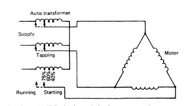
Fig:Squirrel cage induction motor starting
The motor speed depends upon the e.m.f. induced in the rotor and this depends upon the difference in speed between the conductors and the magnetic field. If the load is increased the rotor slows down slightly, causing an increase in induced e.m.f. and thus a greater torque to deal with the increased load.
The motor is almost constant speed over all values of load. It will start against about two times full load torque but draws a starting current of about six times the normal full load current. The starting current can be reduced by having a double cage arrangement on the rotor. Two separated cages are provided, one below the other in the rotor. When starting, the outer high-resistance cage carries almost all the rotor current. As the motor accelerates the low-resistance inner winding takes more and more of the current until it carries the majority. A number of different fixed speeds are possible by pole changing. The speed of an induction motor is proportional to frequency divided by the numbers of pairs of poles. If therefore a switch is provided which can alter the numbers of pairs of poles, then various fixed speeds are possible. The number of poles affects the starting characteristics such that the more poles the less the starting torque to full load torque ratio. Only the induction type of a.c. motor has been described, since it is almost exclusively used in maritime work. Synchronous motors are another type which have been used for electrical propulsion systems but not auxiliary drives.
A number of different arrangements can be used for starting an induction motor. These include direct on-line, star delta, auto transformer and stator resistance. Direct on-line starting is usual where the distribution system can accept the starting current. Where a slow moving high inertia load is involved the starting time must be considered because of the heating effect of the starting current. The star delta starter connects the stator windings first in star and when running changes over to delta.
The star connection results in about half of the line voltage being applied to each phase with therefore a reduction in starting current. The starting torque is also reduced to about one-third of its direct on line value. A rapid change-over to delta is required at about 75% of full load speed when the motor will draw about three-and-a-half times its full load current. The auto transformer starter is used only for large motors. It uses tappings from a transformer to provide, for example, 40%, 60% and 75% of normal voltage (Figure below).
The motor is started on one of the tappings and then quickly switched to full voltage at about 75% full speed. The tapping chosen will depend upon the starting torque required with a 60% tapping giving about 70% of full load torque. A smaller percentage tapping will give a smaller starting torque and vice-versa. The stator resistance starter has a resistance in the stator circuit when the motor is started. An adjustable timing device operates to short circuit this resistance when the motor has reached a particular speed.
Modern electronic techniques enable a.c. induction motors to be used in speed-control systems. The ship's supply, which may not be as stable in voltage or frequency as that ashore, is first rectified to provide a d.c, supply. This is then used as the power supply of an oscillator using high-power electronic devices. These may be thyristors (for powers up to 1.5 M W or more) or transistors (for powers up to a few tens of kilowatts). The high-power oscillator output is controlled in frequency and voltage by a feedback system. The motor speed is varied by changing the oscillator output frequency. The motor current necessary to obtain the desired torque (at small angles of slip) is normally obtained by maintaining the voltage almost proportional to frequency.
Certain protective devices are fitted in the motor circuit to protect against faults such as single phasing, overload or undervoltage. Single phasing occurs when one phase in a three-phase circuit becomes open circuited. The result is excessive currents in ail the windings with, in the case of a delta connected stator running at full load, one winding taking three times its normal load current.
A machine which is running when single phasing occurs will continue to run but with an unbalanced distribution of current. An overload protection device may not trip if the motor is running at less than full load. One method of single phasing protection utilises a temperature-sensitive device which isolates the machine from the supply at some particular winding temperature.
Overload protection devices are also fitted and may be separate or combined with the single phase protection device. They must have a time delay fitted so that operation does not occur during the high starting current period. An undervoltage or 'no volts' protective device ensures that the motor is properly started after a supply failure.
Supplying alternating current to a coil which is free to rotate in a magnetic field will not produce a motor effect since the current is constantly changing direction. Use is therefore made in an induction or squirrel cage motor of a rotating magnetic field produced by three separately phased windings in the stator.
The rotor has a series of copper conductors along its axis which are joined by rings at the ends to form a cage. When the motor is started the rotating magnetic field induces an e.m.f. in the cage and thus a current flow. The current-carrying conductor in a magnetic field produces the motor effect which turns the rotor. The motor speed builds up to a value just less than the speed of rotation of the magnetic field.
Fig:Squirrel cage induction motor starting
The motor speed depends upon the e.m.f. induced in the rotor and this depends upon the difference in speed between the conductors and the magnetic field. If the load is increased the rotor slows down slightly, causing an increase in induced e.m.f. and thus a greater torque to deal with the increased load.
The motor is almost constant speed over all values of load. It will start against about two times full load torque but draws a starting current of about six times the normal full load current. The starting current can be reduced by having a double cage arrangement on the rotor. Two separated cages are provided, one below the other in the rotor. When starting, the outer high-resistance cage carries almost all the rotor current. As the motor accelerates the low-resistance inner winding takes more and more of the current until it carries the majority. A number of different fixed speeds are possible by pole changing. The speed of an induction motor is proportional to frequency divided by the numbers of pairs of poles. If therefore a switch is provided which can alter the numbers of pairs of poles, then various fixed speeds are possible. The number of poles affects the starting characteristics such that the more poles the less the starting torque to full load torque ratio. Only the induction type of a.c. motor has been described, since it is almost exclusively used in maritime work. Synchronous motors are another type which have been used for electrical propulsion systems but not auxiliary drives.
A number of different arrangements can be used for starting an induction motor. These include direct on-line, star delta, auto transformer and stator resistance. Direct on-line starting is usual where the distribution system can accept the starting current. Where a slow moving high inertia load is involved the starting time must be considered because of the heating effect of the starting current. The star delta starter connects the stator windings first in star and when running changes over to delta.
The star connection results in about half of the line voltage being applied to each phase with therefore a reduction in starting current. The starting torque is also reduced to about one-third of its direct on line value. A rapid change-over to delta is required at about 75% of full load speed when the motor will draw about three-and-a-half times its full load current. The auto transformer starter is used only for large motors. It uses tappings from a transformer to provide, for example, 40%, 60% and 75% of normal voltage (Figure below).
The motor is started on one of the tappings and then quickly switched to full voltage at about 75% full speed. The tapping chosen will depend upon the starting torque required with a 60% tapping giving about 70% of full load torque. A smaller percentage tapping will give a smaller starting torque and vice-versa. The stator resistance starter has a resistance in the stator circuit when the motor is started. An adjustable timing device operates to short circuit this resistance when the motor has reached a particular speed.
Modern electronic techniques enable a.c. induction motors to be used in speed-control systems. The ship's supply, which may not be as stable in voltage or frequency as that ashore, is first rectified to provide a d.c, supply. This is then used as the power supply of an oscillator using high-power electronic devices. These may be thyristors (for powers up to 1.5 M W or more) or transistors (for powers up to a few tens of kilowatts). The high-power oscillator output is controlled in frequency and voltage by a feedback system. The motor speed is varied by changing the oscillator output frequency. The motor current necessary to obtain the desired torque (at small angles of slip) is normally obtained by maintaining the voltage almost proportional to frequency.
Certain protective devices are fitted in the motor circuit to protect against faults such as single phasing, overload or undervoltage. Single phasing occurs when one phase in a three-phase circuit becomes open circuited. The result is excessive currents in ail the windings with, in the case of a delta connected stator running at full load, one winding taking three times its normal load current.
A machine which is running when single phasing occurs will continue to run but with an unbalanced distribution of current. An overload protection device may not trip if the motor is running at less than full load. One method of single phasing protection utilises a temperature-sensitive device which isolates the machine from the supply at some particular winding temperature.
Overload protection devices are also fitted and may be separate or combined with the single phase protection device. They must have a time delay fitted so that operation does not occur during the high starting current period. An undervoltage or 'no volts' protective device ensures that the motor is properly started after a supply failure.
No comments:
Post a Comment