How a D.C. current is produced ?
A current is produced when a single coil of wire is rotated in a magnetic field. When the current is collected using a ring which is split into two halves (a commutator), a direct or single direction current is produced. The current produced may be increased by the use of many turns of wire and additional magnetic fields.
With many coils connected to the commutator, sparking will occur as the current collecting brushes move across the insulated segments. Commutating poles or interpoles are used to reduce this sparking. They are in fact electromagnets having a polarity the same as the main pole which follows in the direction of rotation.
The magnetic field between the poles is produced by what are known as 'field coils'. These coils are excited or energised by the current produced in the machine. The soft iron core of the field coils retains some magnetism which enables a preliminary current generation to build up eventually to the full machine output. The field windings can be connected to the output current in a number of ways—shunt, series or compound. The compound wound arrangement is usual since it provides the best voltage characteristics.
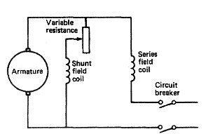
Fig:D.C. generators field connection
The compound wound generator has two sets of field coils . The shunt coil has many turns of fine wire and the series coil has a few turns of heavy wire. The shunt field produces full voltage on no-load which falls off as the load current increases. The series field creates an increase in voltage as the load increases. Properly combined or compounded the result is a fairly constant voltage over a range of load (Figure below).
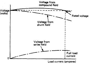
Fig:D.C. generators characteristic curves
Direct current distribution
The generated supply is provided to conductors known as 'bus-bars' which are located behind the main switchboard. The supply then passes through circuit breakers to auxiliaries directly or to section or distribution boards. A circuit breaker is an isolating switch. A section board is a grouping of electrical services fed from the main board. A distribution board feeds minor supplies such as lighting and may itself be fed from the main board or a section board. The distribution system is shown in diagram
A two wire system is usual to provide a supply and return to each item of equipment. An earth lead would be the only electrical connection between any item of equipment and the ship's structure. With compound wound generators a third bus-bar would be introduced as the equalising connection between machines.
A fuse is a type of switch which isolates a circuit if an excessive current flows. To reconnect the circuit, after discovering the cause of the overload, the fuse must be rewired or replaced. The fuse is in effect a weak link in the circuit designed to break and protect equipment from damaging high currents. A semi-enclosed or rewirable fuse will have provision for a wire to be replaced after it has burnt out. The correct rating of fuse wire should be replaced within the holder to reinstate the circuit. A cartridge fuse has the wire enclosed within a ceramic body and it is not rewirable. A 'blown' cartridge fuse must be replaced by a new one, The cartridge fuse is to be preferred since the fusing current value is more reliable than for a rewirable type.
A circuit breaker is an isolating switch which also functions as a fuse. It has two designed ratings: one of the normal safe working current, the other the overload current. The breaker is closed against the action of a spring to make the circuit and supply the section board or auxiliary. A trip mechanism opens the breaker, a fast opening being ensured by the spring. When desired the breaker is tripped or opened manually. It will also open if the overload current rating is exceeded for a period of time.
A delay mechanism prevents the breaker opening for short-period overload currents. The circuit breaker opens or closes both supply and return leads in the circuit. Where a circuit breaker feeds the generator supply to the bus-bars a third 'make-or-break' arm will be provided for the equaliser connection.
Preferential tripping is a means of retaining essential electrical supplies. In the event that a generator cannot supply all the load then non-essential loads are disconnected by preferential trips. The intention is to reduce the generator load while ensuring essential equipment such as steering gear, navigation lights, etc., retains its electrical supply. Various circuit faults can occur as a result of either a break in the conductor (cable) or a break in the insulation. An open-circuit fault results from a break in the conductor and no current flow will take place, A short-circuit fault is due to two breaks in the insulation on, for example, adjacent conductors. The two conductors are connected and a large current flow takes place. An earth fault occurs when a break in the insulation permits the conductor to touch an earthed metal enclosure (or the hull).
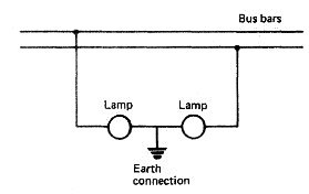
Fig:D.C. generators Earth lamp circuit
Earth faults are usually detected by the use of earth indicating lamps. Two lamps are used, each rated for the full system voltage, but connected in series across the system with the mid point earthed , If the system is correctly insulated then both lamps will glow at half brilliance. The lamps are placed close together to enable a comparison to be made. A direct earth in one pole will short circuit its lamp, causing the other to shine brighdy. A slight insulation breakdown would produce a difference in bulb brightness between the two. Where an earth fault is detected the circuit breakers for each separate circuit must be opened in turn until the fault location is discovered. The particular section or distribution box would then have to have its circuits investigated one by one to locate the fault and enable its correction.
Direct current supply
The supply to a distribution system will usually come from two or more generators operating in parallel. Each generator must be provided with certain protective devices to ensure against reverse currents, low voltage or an overcurrent. There must also be ammeters and voltmeters in the circuits to enable paralleling to take place.
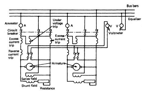
Fig:Protective trips for the parallel operation of two d,c. generators
The circuit for two generators operating in parallel is shown in Figure above. A triple-pole circuit breaker connects the supply to the bus-bars and also the equaliser bus-bar. The arrangement of the various protective trips can be seen, with excess current protection being provided in each pole. The reverse current trip prevents the generator operating as a motor if, for instance, the prime mover stopped.
The voltmeters and ammeters are provided in the generator supply circuits for paralleling purposes. A voltmeter is positioned across the bus-bars to indicate their voltage. Consider the situation where one generator is supplying the bus-bar system and a second generator is to be paralleled with it. The second machine is run up to speed and its field current adjusted until the two machines are at the same voltage. The circuit breaker connecting the second machine to the bus-bar can now be closed and the Field current adjusted to enable the generator to take its share of the load. When the load is evenly shared the two machines can then be left to operate in parallel. The equalising connection will cater for any slight changes in load sharing that occur.
A current is produced when a single coil of wire is rotated in a magnetic field. When the current is collected using a ring which is split into two halves (a commutator), a direct or single direction current is produced. The current produced may be increased by the use of many turns of wire and additional magnetic fields.
With many coils connected to the commutator, sparking will occur as the current collecting brushes move across the insulated segments. Commutating poles or interpoles are used to reduce this sparking. They are in fact electromagnets having a polarity the same as the main pole which follows in the direction of rotation.
The magnetic field between the poles is produced by what are known as 'field coils'. These coils are excited or energised by the current produced in the machine. The soft iron core of the field coils retains some magnetism which enables a preliminary current generation to build up eventually to the full machine output. The field windings can be connected to the output current in a number of ways—shunt, series or compound. The compound wound arrangement is usual since it provides the best voltage characteristics.
Fig:D.C. generators field connection
The compound wound generator has two sets of field coils . The shunt coil has many turns of fine wire and the series coil has a few turns of heavy wire. The shunt field produces full voltage on no-load which falls off as the load current increases. The series field creates an increase in voltage as the load increases. Properly combined or compounded the result is a fairly constant voltage over a range of load (Figure below).
Fig:D.C. generators characteristic curves
Direct current distribution
The generated supply is provided to conductors known as 'bus-bars' which are located behind the main switchboard. The supply then passes through circuit breakers to auxiliaries directly or to section or distribution boards. A circuit breaker is an isolating switch. A section board is a grouping of electrical services fed from the main board. A distribution board feeds minor supplies such as lighting and may itself be fed from the main board or a section board. The distribution system is shown in diagram
A two wire system is usual to provide a supply and return to each item of equipment. An earth lead would be the only electrical connection between any item of equipment and the ship's structure. With compound wound generators a third bus-bar would be introduced as the equalising connection between machines.
A fuse is a type of switch which isolates a circuit if an excessive current flows. To reconnect the circuit, after discovering the cause of the overload, the fuse must be rewired or replaced. The fuse is in effect a weak link in the circuit designed to break and protect equipment from damaging high currents. A semi-enclosed or rewirable fuse will have provision for a wire to be replaced after it has burnt out. The correct rating of fuse wire should be replaced within the holder to reinstate the circuit. A cartridge fuse has the wire enclosed within a ceramic body and it is not rewirable. A 'blown' cartridge fuse must be replaced by a new one, The cartridge fuse is to be preferred since the fusing current value is more reliable than for a rewirable type.
A circuit breaker is an isolating switch which also functions as a fuse. It has two designed ratings: one of the normal safe working current, the other the overload current. The breaker is closed against the action of a spring to make the circuit and supply the section board or auxiliary. A trip mechanism opens the breaker, a fast opening being ensured by the spring. When desired the breaker is tripped or opened manually. It will also open if the overload current rating is exceeded for a period of time.
A delay mechanism prevents the breaker opening for short-period overload currents. The circuit breaker opens or closes both supply and return leads in the circuit. Where a circuit breaker feeds the generator supply to the bus-bars a third 'make-or-break' arm will be provided for the equaliser connection.
Preferential tripping is a means of retaining essential electrical supplies. In the event that a generator cannot supply all the load then non-essential loads are disconnected by preferential trips. The intention is to reduce the generator load while ensuring essential equipment such as steering gear, navigation lights, etc., retains its electrical supply. Various circuit faults can occur as a result of either a break in the conductor (cable) or a break in the insulation. An open-circuit fault results from a break in the conductor and no current flow will take place, A short-circuit fault is due to two breaks in the insulation on, for example, adjacent conductors. The two conductors are connected and a large current flow takes place. An earth fault occurs when a break in the insulation permits the conductor to touch an earthed metal enclosure (or the hull).
Fig:D.C. generators Earth lamp circuit
Earth faults are usually detected by the use of earth indicating lamps. Two lamps are used, each rated for the full system voltage, but connected in series across the system with the mid point earthed , If the system is correctly insulated then both lamps will glow at half brilliance. The lamps are placed close together to enable a comparison to be made. A direct earth in one pole will short circuit its lamp, causing the other to shine brighdy. A slight insulation breakdown would produce a difference in bulb brightness between the two. Where an earth fault is detected the circuit breakers for each separate circuit must be opened in turn until the fault location is discovered. The particular section or distribution box would then have to have its circuits investigated one by one to locate the fault and enable its correction.
Direct current supply
The supply to a distribution system will usually come from two or more generators operating in parallel. Each generator must be provided with certain protective devices to ensure against reverse currents, low voltage or an overcurrent. There must also be ammeters and voltmeters in the circuits to enable paralleling to take place.
Fig:Protective trips for the parallel operation of two d,c. generators
The circuit for two generators operating in parallel is shown in Figure above. A triple-pole circuit breaker connects the supply to the bus-bars and also the equaliser bus-bar. The arrangement of the various protective trips can be seen, with excess current protection being provided in each pole. The reverse current trip prevents the generator operating as a motor if, for instance, the prime mover stopped.
The voltmeters and ammeters are provided in the generator supply circuits for paralleling purposes. A voltmeter is positioned across the bus-bars to indicate their voltage. Consider the situation where one generator is supplying the bus-bar system and a second generator is to be paralleled with it. The second machine is run up to speed and its field current adjusted until the two machines are at the same voltage. The circuit breaker connecting the second machine to the bus-bar can now be closed and the Field current adjusted to enable the generator to take its share of the load. When the load is evenly shared the two machines can then be left to operate in parallel. The equalising connection will cater for any slight changes in load sharing that occur.
No comments:
Post a Comment