Direct current motors
When a current is supplied to a single coil of wire in a magnetic field a force is created which rotates the coil. This is a similar situation to the generation of current by a coil moving in a magnetic field. In fact generators and motors are almost interchangeable, depending upon which two of magnetic field, current and motion are provided.
Additional coils of wire and more magnetic fields produce a more efficient motor. Interpoles are fitted to reduce sparking but now have opposite polarity to the next main pole in the direction of rotation, When rotating the armature acts as a generator and produces current in the reverse direction to the supply. This is known as back e.m.f. (electromotive force) and causes a voltage drop across the motor. This back e.m.f. controls the power used by the motor but is not present as the motor is started. As a result, to avoid high starting currents special control circuits or starters are used.
The behaviour of the d.c. motor on load is influenced by the voltage drop across the armature, the magnetic field produced between the poles and the load or torque on the motor. Some of these factors are interdependent. For example, the voltage drop across the armature depends upon the back e.m.f. which depends upon the speed of the motor and the strength of the magnetic field. Shunt, series and compound windings are used to obtain different motor characteristics by varying the above factors.
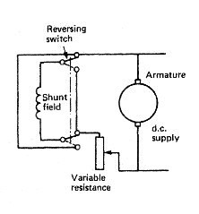
Fig: Shunt wound d.c. motor
The shunt wound motor has field windings connected in parallel with the armature windings. Thus when the motor is operating with a fixed load at constant speed all other factors are constant. An increase in load will cause a drop in speed and therefore a reduction in back e.m.f. A greater current will then flow in the armature windings and the motor power consumption will rise: the magnetic field will be unaffected since it is connected in parallel. Speed reduction is, in practice, very small, which makes the shunt motor an ideal choke for constant-speed variable-load duties.
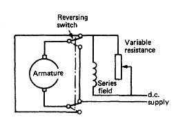
Fig: Series wound d.c. motor
The series motor has field windings connected in series with the armature windings . With this arrangement an increase in load will cause a reduction in speed and a fall in back e.m.f. The increased load current will, however, now increase the magnetic field and therefore the back e.m.f. The motor will finally stabilise at some reduced value of speed. The series motor speed therefore changes considerably with load.
Control of d.c. motors is quite straightforward. The shunt wound motor has a variable resistance in the field circuit, as shown in Figure . This permits variation of the current in the field coils and also the back e.m.f., giving a range of constant speeds. To reverse the motor the field current supply is reversed, as shown in Figure .
One method of speed control for a series wound motor has a variable resistance in parallel with the field coils. Reverse operation is again achieved by reversing the field current supply as shown in Figure .
In operation the shunt wound motor runs at constant speed regardless of load. The series motor runs at a speed determined by the load, the greater the load the slower the speed. Compounding—the use of shunt and series field windings—provides a combination of these characteristics. Starting torque is also important. For a series wound motor the starting torque is high and it reduces as the load increases. This makes the series motor useful for winch and crane applications. It should be noted that a series motor if started on no-load has an infinite speed. Some small amount of compounding is usual to avoid this dangerous occurrence. The shunt wound motor is used where constant speed is required regardless of load; for instance, with fans or pumps. The starting of a d.c. motor requires a circuit arrangement to limit armature current. This is achieved by the use of a starter .
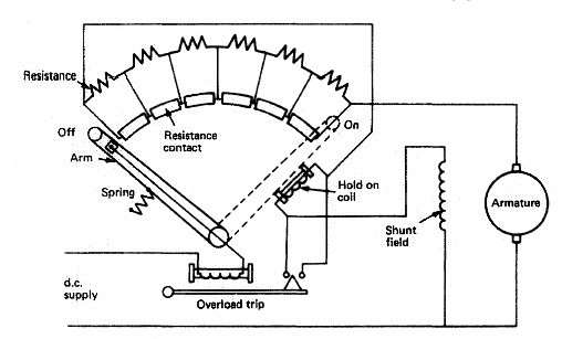
Fig: d.c. motor starter
A number of resistances are provided in the armature and progressively removed as the motor speeds up and back e.m.f. is developed. An arm, as part of the armature circuit, moves over resistance contacts such that a number of resistances are first put into the armature circuit and then progressively removed. The arm must be moved slowly to enable the motor speed and thus the back e.m.f. to build up. At the final contact no resistance is in the armature circuit. A 'hold on' or 'no volts' coil holds the starter arm in place while there is current in the armature circuit.
If a loss of supply occurs the arm will be released and returned to the 'off position by a spring. The motor must then be started again in the normal way. An overload trip is also provided which prevents excess current by shorting out the 'hold on* coil and releasing the starter arm. The overload coil has a soft iron core which, when magnetised sufficiently by an excess current, attracts the trip bar which shorts out the hold on coil. This type of starter is known as a 'face plate'; other types make use of contacts without the starting handle but introduce resistance into the armature circuit in much the same way.
When a current is supplied to a single coil of wire in a magnetic field a force is created which rotates the coil. This is a similar situation to the generation of current by a coil moving in a magnetic field. In fact generators and motors are almost interchangeable, depending upon which two of magnetic field, current and motion are provided.
Additional coils of wire and more magnetic fields produce a more efficient motor. Interpoles are fitted to reduce sparking but now have opposite polarity to the next main pole in the direction of rotation, When rotating the armature acts as a generator and produces current in the reverse direction to the supply. This is known as back e.m.f. (electromotive force) and causes a voltage drop across the motor. This back e.m.f. controls the power used by the motor but is not present as the motor is started. As a result, to avoid high starting currents special control circuits or starters are used.
The behaviour of the d.c. motor on load is influenced by the voltage drop across the armature, the magnetic field produced between the poles and the load or torque on the motor. Some of these factors are interdependent. For example, the voltage drop across the armature depends upon the back e.m.f. which depends upon the speed of the motor and the strength of the magnetic field. Shunt, series and compound windings are used to obtain different motor characteristics by varying the above factors.
Fig: Shunt wound d.c. motor
The shunt wound motor has field windings connected in parallel with the armature windings. Thus when the motor is operating with a fixed load at constant speed all other factors are constant. An increase in load will cause a drop in speed and therefore a reduction in back e.m.f. A greater current will then flow in the armature windings and the motor power consumption will rise: the magnetic field will be unaffected since it is connected in parallel. Speed reduction is, in practice, very small, which makes the shunt motor an ideal choke for constant-speed variable-load duties.
Fig: Series wound d.c. motor
The series motor has field windings connected in series with the armature windings . With this arrangement an increase in load will cause a reduction in speed and a fall in back e.m.f. The increased load current will, however, now increase the magnetic field and therefore the back e.m.f. The motor will finally stabilise at some reduced value of speed. The series motor speed therefore changes considerably with load.
Control of d.c. motors is quite straightforward. The shunt wound motor has a variable resistance in the field circuit, as shown in Figure . This permits variation of the current in the field coils and also the back e.m.f., giving a range of constant speeds. To reverse the motor the field current supply is reversed, as shown in Figure .
One method of speed control for a series wound motor has a variable resistance in parallel with the field coils. Reverse operation is again achieved by reversing the field current supply as shown in Figure .
In operation the shunt wound motor runs at constant speed regardless of load. The series motor runs at a speed determined by the load, the greater the load the slower the speed. Compounding—the use of shunt and series field windings—provides a combination of these characteristics. Starting torque is also important. For a series wound motor the starting torque is high and it reduces as the load increases. This makes the series motor useful for winch and crane applications. It should be noted that a series motor if started on no-load has an infinite speed. Some small amount of compounding is usual to avoid this dangerous occurrence. The shunt wound motor is used where constant speed is required regardless of load; for instance, with fans or pumps. The starting of a d.c. motor requires a circuit arrangement to limit armature current. This is achieved by the use of a starter .
Fig: d.c. motor starter
A number of resistances are provided in the armature and progressively removed as the motor speeds up and back e.m.f. is developed. An arm, as part of the armature circuit, moves over resistance contacts such that a number of resistances are first put into the armature circuit and then progressively removed. The arm must be moved slowly to enable the motor speed and thus the back e.m.f. to build up. At the final contact no resistance is in the armature circuit. A 'hold on' or 'no volts' coil holds the starter arm in place while there is current in the armature circuit.
If a loss of supply occurs the arm will be released and returned to the 'off position by a spring. The motor must then be started again in the normal way. An overload trip is also provided which prevents excess current by shorting out the 'hold on* coil and releasing the starter arm. The overload coil has a soft iron core which, when magnetised sufficiently by an excess current, attracts the trip bar which shorts out the hold on coil. This type of starter is known as a 'face plate'; other types make use of contacts without the starting handle but introduce resistance into the armature circuit in much the same way.
No comments:
Post a Comment